문제사항
값 누락 문제
- BLE bluetooth의 경우 패킷당 최대 20바이트 전송을 하기 때문에 값이 누락됩니다.
- 20바이트 이상의 데이터를 전송하려면 디바이스 및 유니티가 전송 방식을 합의 하여 같이 수정해야합니다.
값이 상이한 문제
- 필요한 값과 실제 전달되고 있는 값이 상이하여 결과가 원하는 대로 나오지 않습니다.
- 값을 일방적으로 반영하여 드릴 수는 있으나 의미있는 결과가 나오지 않습니다.
- 실제 전달되고 있는 값을 연산하여 필요한 값으로 만들어서 전달해 주셔야합니다.
필요한 값
- 디바이스의 x,y,z 회전 각도 값 : 오일러 각 또는 쿼터니언
- 디바이스의 x,y,z 이동량 : 회전 각도 값이 반영된 이동량
실제 전달되고 있는 값
- 자이로센서 : x,y,z 회전 가속도 값
- 가속도센서 : x,y,z 직선 가속도 값
- 지자기센서 : x,y,z 자기장의 방향 성분
전달주신 참고자료
MPU9250 9축센서 라이브러리 참고자료
//센서 로우 데이터를 통해 만들어진 회전량 : 센싱된 값을 연산을 통해 사용할수 있는 값으로 변환한 결과 입니다.
float getRoll() const;
float getPitch() const;
float getYaw() const;

float getEulerX() const;
float getEulerY() const;
float getEulerZ() const;

//쿼터니언 (짐벌락 방지)
float getQuaternionX() const;
float getQuaternionY() const;
float getQuaternionZ() const;
float getQuaternionW() const;

//센서 로우 데이터 : 연산을 거치지 않은 센서를 통에 얻을 수 있는 날(生)값입니다. 여러가지 문제가 동반 될 수 있습니다.
float getAccX() const;
float getAccY() const;
float getAccZ() const;
float getGyroX() const;
float getGyroY() const;
float getGyroZ() const;
float getMagX() const;
float getMagY() const;
float getMagZ() const;

//중력 성분을 제거한 선형 가속도
float getLinearAccX() const;
float getLinearAccY() const;
float getLinearAccZ() const;
- 현재 자이로센서의 x,y,z값을 roll,pitch,yaw로 사용하고 있는데 이는 서로 다른 종류의 값입니다.
현재 상황
Byte Size: 58
 1, 1,0.05,-0.04,-0.04,0.64,-0.90,0.20,-1620,-70,-773,4.13
Byte Size: 58
 1, 1,0.05,-0.04,-0.02,0.64,-0.90,0.20,-1635,-65,-788,4.14
Byte Size: 58
 1, 1,0.04,-0.04,-0.01,0.63,-0.91,0.20,-1613,-80,-757,4.14
Byte Size: 58
 1, 1,0.04,-0.03,-0.01,0.63,-0.91,0.20,-1632,-57,-770,4.13
Byte Size: 58
 1, 1,0.04,-0.04,-0.02,0.64,-0.91,0.20,-1603,-90,-786,4.14
Byte Size: 58
 1, 1,0.04,-0.04,-0.03,0.62,-0.91,0.19,-1632,-72,-767,4.14
Byte Size: 58
 1, 1,0.04,-0.04,-0.02,0.63,-0.89,0.19,-1635,-95,-757,4.14
Byte Size: 58
 1, 1,0.04,-0.03,-0.02,0.63,-0.91,0.19,-1613,-82,-757,4.13
Byte Size: 58
 1, 1,0.04,-0.03,-0.03,0.63,-0.91,0.20,-1645,-75,-755,4.12
Byte Size: 58
- 스위치(1, 1),자이로센서(0.04,-0.04,-0.03),가속도센서(0.64,-0.90,0.20),지자계센서(-1627,-75,-747),4.11
- 자이로센서에서는 회전가속도 값을 전달 받습니다. 이 값을 그대로 사용하면 큐브가 다음과 같이 작동합니다.
※위 영상은 ‘일부공개’ 영상으로 직접적인 링크를 열지 않으면 유튜브내에서 검색하여 볼수 없는 영상으로 등록되어 있습니다.
영상에서 확인 가능한 문제점
- 회전값 드리프트 : 센서가 캘리브레이션 (오차를 계산하여 offset값 설정) 되어있지 않아서 회전가속도 값에 누적 오차가 생깁니다. 센서를 바닥에 내려놓은 상태(고정 상태)에서도 3D객체가 천천히 회전하는것을 볼 수 있습니다.
- 직선운동 가속도 : 자이로센서 값에 가속도센서값이 반영되어 있지 않아서 직선운동을 할때에도 회전운동을 한것 같은 오차가 생깁니다.
필요 요청사항
- 센서의 캘리브레이션 후 옵셋값이 eeprom등을 통해 유지되어야합니다. (드리프트 방지)
- 센서의 로우값이 아닌 가공된 각도값이 필요합니다.
- 센서의 가속도값이 회전량이 반영된 가속도량(실 공간에서의 위아래 좌우에 해당하는 방향으로의 가속도량)이 필요합니다.
디바이스 처리 절차
- 센서값을 가공하여 회전값으로 변경
- 2버튼 클릭시 x,y,z rotation을 offset 값으로 설정
- offset 반영하여 정면으로 라인출력
- 2버튼 클릭에 따른 표시, 해제(press = enable, release = disable)
- 라인을 디바이스 회전 방향과 일치
- 라인을 디바이스 회전 양과 일치
- 레이캐스트를 이용한 대상표시 (색상변경?)
- 1버튼 클릭시 대상 그랩, 이동
자이로값 -> 오일러
- 센서로 부터 받은 각속도 데이터를 이용하여 오일러 각도를 계산
- 각속도 데이터를 시간에 대해 적분한다
- 이를 이산 시간에서 근사적으로 계산한다.
Byte Size: 82 1, 1,-0.72,0.15,-0.15,-0.66,0.04,-0.04,-0.03,-0.46,-0.07,0.84,-418,1405,-651,4.09 Byte Size: 82 1, 1,-0.72,0.15,-0.15,-0.66,0.05,-0.04,-0.02,-0.46,-0.09,0.83,-411,1417,-662,4.09 Byte Size: 82 1, 1,-0.72,0.15,-0.15,-0.66,0.05,-0.02,-0.02,-0.46,-0.08,0.84,-400,1417,-656,4.09 Byte Size: 82 1, 1,-0.72,0.15,-0.15,-0.66,0.04,-0.04,-0.03,-0.47,-0.06,0.84,-413,1410,-682,4.09 Byte Size: 82 1, 1,-0.72,0.15,-0.15,-0.66,0.05,-0.03,-0.02,-0.47,-0.07,0.85,-408,1430,-675,4.09 - 20자 :
1, 1,-0.72,0.15,-0. -
20자 :
1, 1,98.33,15.35,9. -
1 1 +000 +000 +000 +000
쿼터니언
- 쿼터니언(Quaternion)은 회전을 나타내기 위해 사용되며, 4개의 요소로 구성됩니다: (w, x, y, z). 쿼터니언은 단위 쿼터니언의 형태로 사용되는 것이 일반적이며, 이는 그 노름(norm)이 1인 쿼터니언을 의미합니다.
- 단위 쿼터니언의 경우, 다음 조건을 만족합니다:
- [ w^2 + x^2 + y^2 + z^2 = 1 ]
- 각각의 개별 쿼터니언 요소 (w, x, y, z)의 범위는 다음과 같습니다:
범위
- 기본적으로, 각 요소의 값은 -1부터 1 사이의 값을 가질 수 있습니다:
- ( w in [-1, 1] )
- ( x in [-1, 1] )
- ( y in [-1, 1] )
- ( z in [-1, 1] )
변형
- +2을 해주면 범위가 1~3까지, *1000해서 정수 4자리로
- 역으로 /1000한 다음 -2 해주면 됨
1|1|0000|0000|0000|000011--891--279--277--228,11+492+16+401+773,202401175227340910,20240618,111946412935112239446,21117674078131160,4.12자릿수 부족. 소숫점 0 삭제 상태
    public void setdata(float x, float y, float z, float w)
    {
        bodyQuat = new Quaternion(x,y,z,w);
        diffQuat = Quaternion.Inverse(bodyQuat) * lastQuat ;
		transform.Rotate(diffQuat.eulerAngles, Space.World);
		lastQuat = bodyQuat;
    }
- 쿼터니언 반영. 센서 라이브러리 좌표계랑 유니티 좌표계가 틀려서 Inverse 해서 사용해 주어야 한다는거 같음.
센서 드리프트
#define MPU6050_AXOFFSET -208
#define MPU6050_AYOFFSET 417
#define MPU6050_AZOFFSET 93

#define MPU6050_AXGAIN 4096.0 // AFS_SEL = 2, +/-8g, MPU6050_ACCEL_FS_8
#define MPU6050_AYGAIN 4096.0 // AFS_SEL = 2, +/-8g, MPU6050_ACCEL_FS_8
#define MPU6050_AZGAIN 4096.0 // AFS_SEL = 2, +/-8g, MPU6050_ACCEL_FS_8

#define MPU6050_GXOFFSET 0
#define MPU6050_GYOFFSET 2
#define MPU6050_GZOFFSET 3

#define MPU6050_GXGAIN 16.384 // FS_SEL = 3, +/-2000degree/s, MPU6050_GYRO_FS_2000
#define MPU6050_GYGAIN 16.384 // FS_SEL = 3, +/-2000degree/s, MPU6050_GYRO_FS_2000
#define MPU6050_GZGAIN 16.384 // FS_SEL = 3, +/-2000degree/s, MPU6050_GYRO_FS_2000
켈리브레이션
// Arduino sketch that returns calibration offsets for MPU6050 //   Version 1.1  (31th January 2014)
// Done by Luis Ródenas <luisrodenaslorda@gmail.com>
// Based on the I2Cdev library and previous work by Jeff Rowberg <jeff@rowberg.net>
// Updates (of the library) should (hopefully) always be available at https://github.com/jrowberg/i2cdevlib

// These offsets were meant to calibrate MPU6050's internal DMP, but can be also useful for reading sensors.
// The effect of temperature has not been taken into account so I can't promise that it will work if you
// calibrate indoors and then use it outdoors. Best is to calibrate and use at the same room temperature.

/* ==========  LICENSE  ==================================
 I2Cdev device library code is placed under the MIT license
 Copyright (c) 2011 Jeff Rowberg

 Permission is hereby granted, free of charge, to any person obtaining a copy
 of this software and associated documentation files (the "Software"), to deal
 in the Software without restriction, including without limitation the rights
 to use, copy, modify, merge, publish, distribute, sublicense, and/or sell
 copies of the Software, and to permit persons to whom the Software is
 furnished to do so, subject to the following conditions:

 The above copyright notice and this permission notice shall be included in
 all copies or substantial portions of the Software.

 THE SOFTWARE IS PROVIDED "AS IS", WITHOUT WARRANTY OF ANY KIND, EXPRESS OR
 IMPLIED, INCLUDING BUT NOT LIMITED TO THE WARRANTIES OF MERCHANTABILITY,
 FITNESS FOR A PARTICULAR PURPOSE AND NONINFRINGEMENT. IN NO EVENT SHALL THE
 AUTHORS OR COPYRIGHT HOLDERS BE LIABLE FOR ANY CLAIM, DAMAGES OR OTHER
 LIABILITY, WHETHER IN AN ACTION OF CONTRACT, TORT OR OTHERWISE, ARISING FROM,
 OUT OF OR IN CONNECTION WITH THE SOFTWARE OR THE USE OR OTHER DEALINGS IN
 THE SOFTWARE.
 =========================================================
 */

// I2Cdev and MPU6050 must be installed as libraries
#include "I2Cdev.h"
#include "MPU6050.h"
#include "Wire.h"

///////////////////////////////////   CONFIGURATION   /////////////////////////////
//Change this 3 variables if you want to fine tune the skecth to your needs.
int buffersize=1000;     //Amount of readings used to average, make it higher to get more precision but sketch will be slower  (default:1000)
int acel_deadzone=8;     //Acelerometer error allowed, make it lower to get more precision, but sketch may not converge  (default:8)
int giro_deadzone=1;     //Giro error allowed, make it lower to get more precision, but sketch may not converge  (default:1)

// default I2C address is 0x68
// specific I2C addresses may be passed as a parameter here
// AD0 low = 0x68 (default for InvenSense evaluation board)
// AD0 high = 0x69
//MPU6050 accelgyro;
MPU6050 accelgyro(0x68); // <-- use for AD0 high

int16_t ax, ay, az,gx, gy, gz;

int mean_ax,mean_ay,mean_az,mean_gx,mean_gy,mean_gz,state=0;
int ax_offset,ay_offset,az_offset,gx_offset,gy_offset,gz_offset;

///////////////////////////////////   SETUP   ////////////////////////////////////
void setup() {
  // join I2C bus (I2Cdev library doesn't do this automatically)
  Wire.begin();
  // COMMENT NEXT LINE IF YOU ARE USING ARDUINO DUE
  TWBR = 24; // 400kHz I2C clock (200kHz if CPU is 8MHz). Leonardo measured 250kHz.

  // initialize serial communication
  Serial.begin(115200);

  // initialize device
  accelgyro.initialize();

  // wait for ready
  while (Serial.available() && Serial.read()); // empty buffer
  while (!Serial.available()){
    Serial.println(F("Send any character to start sketch.\n"));
    delay(1500);
  }
  while (Serial.available() && Serial.read()); // empty buffer again

  // start message
  Serial.println("\nMPU6050 Calibration Sketch");
  delay(2000);
  Serial.println("\nYour MPU6050 should be placed in horizontal position, with package letters facing up. \nDon't touch it until you see a finish message.\n");
  delay(3000);
  // verify connection
  Serial.println(accelgyro.testConnection() ? "MPU6050 connection successful" : "MPU6050 connection failed");
  delay(1000);
  // reset offsets
  accelgyro.setXAccelOffset(0);
  accelgyro.setYAccelOffset(0);
  accelgyro.setZAccelOffset(0);
  accelgyro.setXGyroOffset(0);
  accelgyro.setYGyroOffset(0);
  accelgyro.setZGyroOffset(0);
}

///////////////////////////////////   LOOP   ////////////////////////////////////
void loop() {
  if (state==0){
    Serial.println("\nReading sensors for first time...");
    meansensors();
    state++;
    delay(1000);
  }

  if (state==1) {
    Serial.println("\nCalculating offsets...");
    calibration();
    state++;
    delay(1000);
  }

  if (state==2) {
    meansensors();
    Serial.println("\nFINISHED!");
    Serial.print("\nSensor readings with offsets:\t");
    Serial.print(mean_ax);
    Serial.print("\t");
    Serial.print(mean_ay);
    Serial.print("\t");
    Serial.print(mean_az);
    Serial.print("\t");
    Serial.print(mean_gx);
    Serial.print("\t");
    Serial.print(mean_gy);
    Serial.print("\t");
    Serial.println(mean_gz);
    Serial.print("Your offsets:\t");
    Serial.print(ax_offset);
    Serial.print("\t");
    Serial.print(ay_offset);
    Serial.print("\t");
    Serial.print(az_offset);
    Serial.print("\t");
    Serial.print(gx_offset);
    Serial.print("\t");
    Serial.print(gy_offset);
    Serial.print("\t");
    Serial.println(gz_offset);
    Serial.println("\nData is printed as: acelX acelY acelZ giroX giroY giroZ");
    Serial.println("Check that your sensor readings are close to 0 0 16384 0 0 0");
    Serial.println("If calibration was succesful write down your offsets so you can set them in your projects using something similar to mpu.setXAccelOffset(youroffset)");
    while (1);
  }
}

///////////////////////////////////   FUNCTIONS   ////////////////////////////////////
void meansensors(){
  long i=0,buff_ax=0,buff_ay=0,buff_az=0,buff_gx=0,buff_gy=0,buff_gz=0;

  while (i<(buffersize+101)){
    // read raw accel/gyro measurements from device
    accelgyro.getMotion6(&ax, &ay, &az, &gx, &gy, &gz);

    if (i>100 && i<=(buffersize+100)){ //First 100 measures are discarded
      buff_ax=buff_ax+ax;
      buff_ay=buff_ay+ay;
      buff_az=buff_az+az;
      buff_gx=buff_gx+gx;
      buff_gy=buff_gy+gy;
      buff_gz=buff_gz+gz;
    }
    if (i==(buffersize+100)){
      mean_ax=buff_ax/buffersize;
      mean_ay=buff_ay/buffersize;
      mean_az=buff_az/buffersize;
      mean_gx=buff_gx/buffersize;
      mean_gy=buff_gy/buffersize;
      mean_gz=buff_gz/buffersize;
    }
    i++;
    delay(2); //Needed so we don't get repeated measures
  }
}

void calibration(){
  ax_offset=-mean_ax/8;
  ay_offset=-mean_ay/8;
  az_offset=(16384-mean_az)/8;

  gx_offset=-mean_gx/4;
  gy_offset=-mean_gy/4;
  gz_offset=-mean_gz/4;
  while (1){
    int ready=0;
    accelgyro.setXAccelOffset(ax_offset);
    accelgyro.setYAccelOffset(ay_offset);
    accelgyro.setZAccelOffset(az_offset);

    accelgyro.setXGyroOffset(gx_offset);
    accelgyro.setYGyroOffset(gy_offset);
    accelgyro.setZGyroOffset(gz_offset);

    meansensors();
    Serial.println("...");

    if (abs(mean_ax)<=acel_deadzone) ready++;
    else ax_offset=ax_offset-mean_ax/acel_deadzone;

    if (abs(mean_ay)<=acel_deadzone) ready++;
    else ay_offset=ay_offset-mean_ay/acel_deadzone;

    if (abs(16384-mean_az)<=acel_deadzone) ready++;
    else az_offset=az_offset+(16384-mean_az)/acel_deadzone;

    if (abs(mean_gx)<=giro_deadzone) ready++;
    else gx_offset=gx_offset-mean_gx/(giro_deadzone+1);

    if (abs(mean_gy)<=giro_deadzone) ready++;
    else gy_offset=gy_offset-mean_gy/(giro_deadzone+1);

    if (abs(mean_gz)<=giro_deadzone) ready++;
    else gz_offset=gz_offset-mean_gz/(giro_deadzone+1);

    if (ready==6) break;
  }
}
- I2C library : https://github.com/jrowberg/i2cdevlib/archive/master.zip
- Download the i2cdevlib project
- Unzip the downloaded file.
- Select Sketch > Include Libraries > Add .ZIP Library from the Arduino IDE’s menus.
- Select the “Arduino/I2Cdev” subfolder of the unzipped folder.
- Click the Open button.
Sensor readings with offsets:	-16	-6	16391	1	0	0
Your offsets:	-408	1472	1822	-80	57	45

Sensor readings with offsets:	3	0	16384	0	-2	0
Your offsets:	-400	1474	1822	-78	59	42

Sensor readings with offsets:	-7	-1	16373	-2	-5	-1
Your offsets:	-597	1579	5911	-80	56	43
//센서 위아래를 뒤집었을때

Sensor readings with offsets:	0	0	16387	1	3	1
Your offsets:	-385	1478	1830	-73	58	45

Data is printed as: acelX acelY acelZ giroX giroY giroZ
Check that your sensor readings are close to 0 0 16384 0 0 0
#define MPU6050_AXOFFSET -208
#define MPU6050_AYOFFSET 417
#define MPU6050_AZOFFSET 93

#define MPU6050_AXGAIN 4096.0 // AFS_SEL = 2, +/-8g, MPU6050_ACCEL_FS_8
#define MPU6050_AYGAIN 4096.0 // AFS_SEL = 2, +/-8g, MPU6050_ACCEL_FS_8
#define MPU6050_AZGAIN 4096.0 // AFS_SEL = 2, +/-8g, MPU6050_ACCEL_FS_8

#define MPU6050_GXOFFSET 0
#define MPU6050_GYOFFSET 2
#define MPU6050_GZOFFSET 3

#define MPU6050_GXGAIN 16.384 // FS_SEL = 3, +/-2000degree/s, MPU6050_GYRO_FS_2000
#define MPU6050_GYGAIN 16.384 // FS_SEL = 3, +/-2000degree/s, MPU6050_GYRO_FS_2000
#define MPU6050_GZGAIN 16.384 // FS_SEL = 3, +/-2000degree/s, MPU6050_GYRO_FS_2000
//원래 값

---

#define MPU6050_AXOFFSET -400
#define MPU6050_AYOFFSET 1474
#define MPU6050_AZOFFSET 1822

#define MPU6050_GXOFFSET -78
#define MPU6050_GYOFFSET 59
#define MPU6050_GZOFFSET 42
- USB 디버깅 권한 승인 취소
2024-06-24 중간보고
- 센서에서 전달되는 로우값 자체가 틀어져있습니다.
- 회전 방향에 따른 짐벌락도 발생하는것 같습니다.
- 틀어진 회전축을 재계산하여 소프트웨어로 맞추어도 조금만 움직이면 (움직이지 않고 기다려도) 축이 틀어집니다.
- 짐벌락 현상으로 추청되는 원인으로 인하여 회전시 축이 맞지 않고 돌아가 버립니다.
2024-06-27 협조요청
센서 오차값에 따른 offset값 반영요청
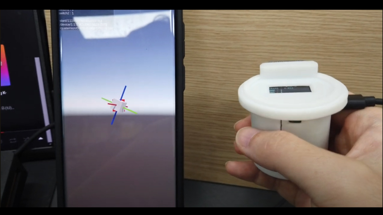
- 시작시 - 디바이스로 부터 받은 센서값이 기울어져 있습니다.
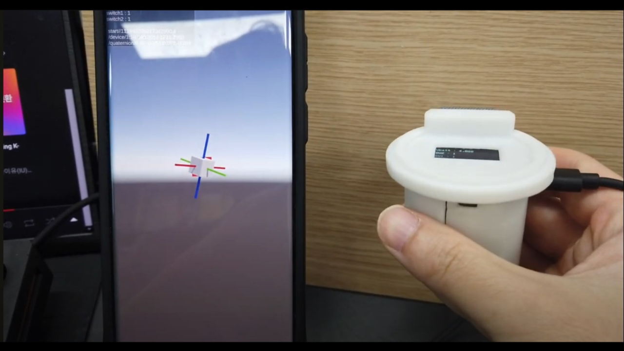
- 디바이스를 조금 움직이고 4초 뒤 시작했을 때와 축이 다릅니다.
- 센서 자체에 오차를 측정하고 offset 값을 설정하여 측정값 drift(밀림)현상을 최소화 해야합니다.
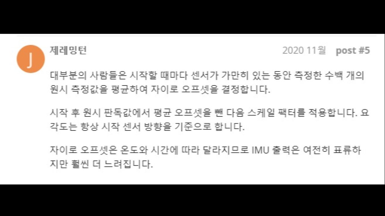
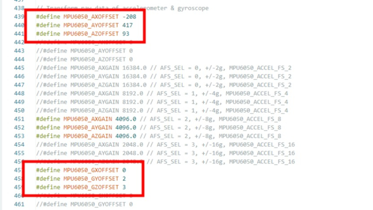
- 전달해 주신 소스코드내에 offset값이 기록되어 있기는 하지만 drift가 계속 발생하는 것으로 보아 올바른 값이 입력되어 있다고 생각하기 어렵습니다.
- 다음은 제가 가진 소스코드로 제가 측정한 offset 값입니다.
Sensor readings with offsets:	-16	-6	16391	1	0	0
Your offsets:	-408	1472	1822	-80	57	45

Sensor readings with offsets:	3	0	16384	0	-2	0
Your offsets:	-400	1474	1822	-78	59	42

Sensor readings with offsets:	0	0	16387	1	3	1
Your offsets:	-385	1478	1830	-73	58	45

Data is printed as: acelX acelY acelZ giroX giroY giroZ
Check that your sensor readings are close to 0 0 16384 0 0 0
- 이를 반영하여 offset값을 다음과 같이 변경 하였으나 소스코드 자체가 달라서 문제가 해결되지 않았습니다.
#define MPU6050_AXOFFSET -400
#define MPU6050_AYOFFSET 1474
#define MPU6050_AZOFFSET 1822

#define MPU6050_GXOFFSET -78
#define MPU6050_GYOFFSET 59
#define MPU6050_GZOFFSET 42
짐벌락 문제로 인한 쿼터니언값 요청
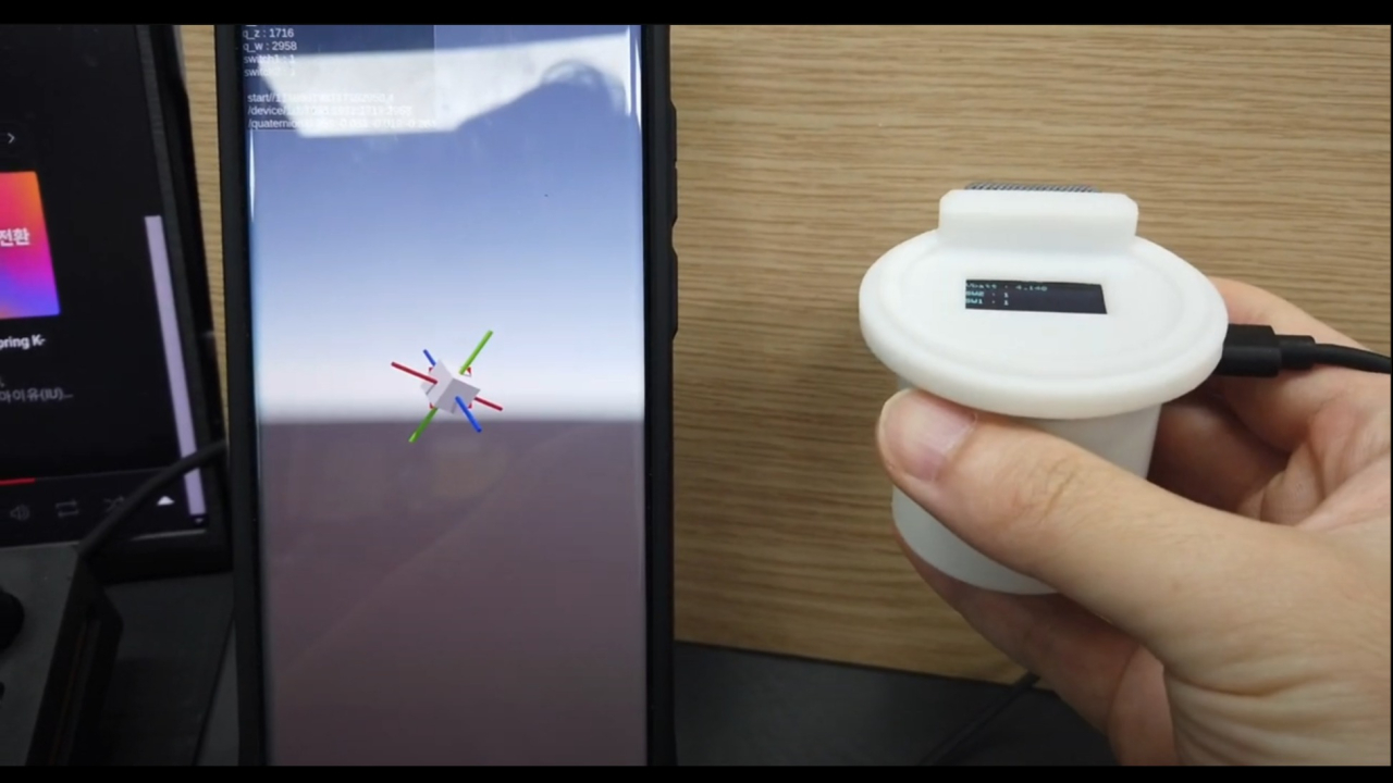
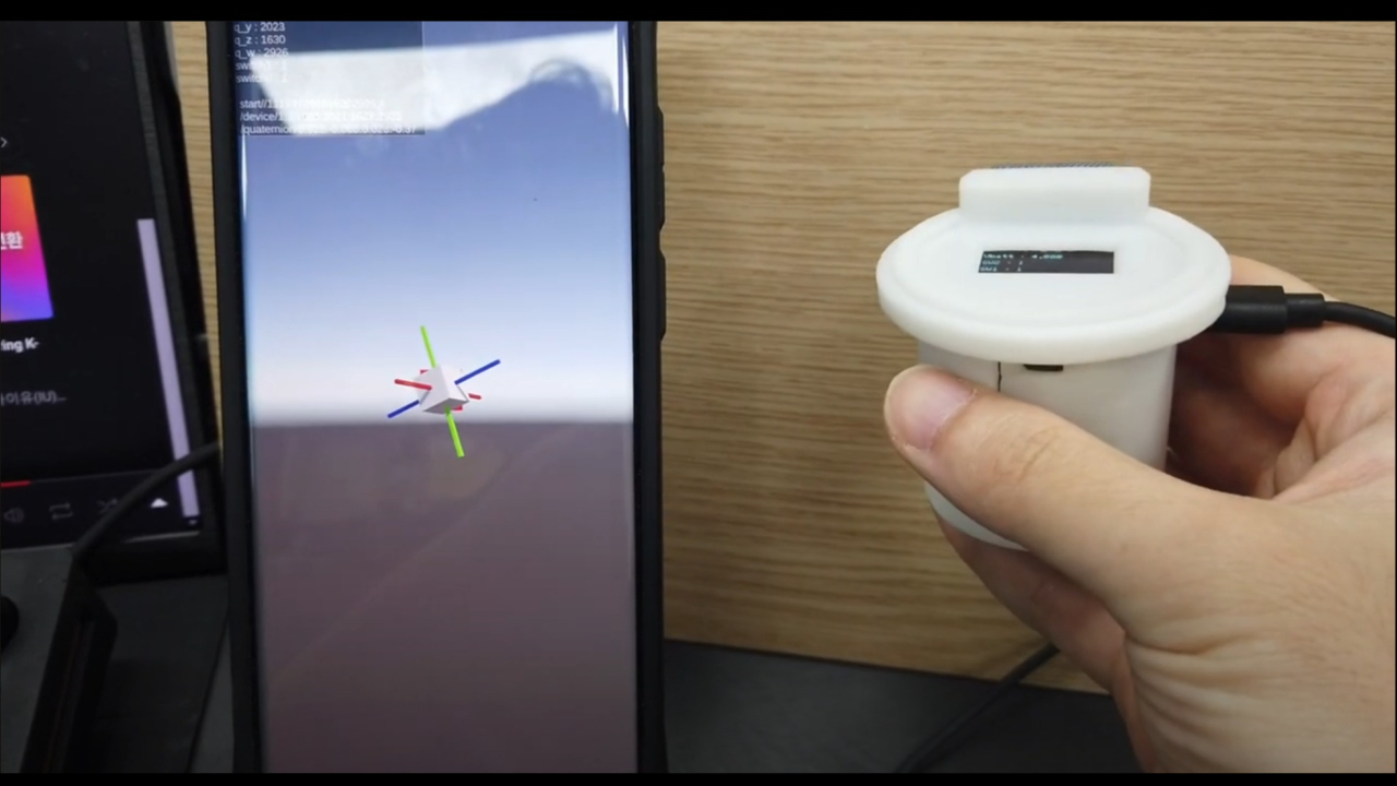
- 디바이스를 든 손을 시계방향으로 한바퀴 회전한 뒤의 결과 입니다.
- 각 축을 색깔로 표시한 막대를 보시면 축이 완전히 틀어집니다.
- 이는 오일러 앵글의 짐벌락에 의해 발생하는 것으로 짐벌락에 관한 설명은 다음의 영상에서 보실 수 있습니다.
- x,y,z축을 순서대로 반영하는 오일러각 계산법으로 축계산을 하면 측정 축이 겹치는 환경에서 축값이 잘못 계산되는 현상이 있습니다.
- 따라서 쿼터니언으로 만들어진 값을 전달받아야 합니다.
왜 센서 기본값으로 직접 쿼터니언 계산을 하지 않는가?
- 센서 RAW값은 -1~+1의 ‘이전 위치에서 얼마나 각회전을 하였는가’ 값으로 이루어져 있습니다. - 변화량을 전달합니다.
- Bluetooth 통신상 통신이 정확한 시간으로 동일한게 데이터를 전달하지 않고. 때에 따라서는 누락되거나 디바이스부하로 인한 지연, 컴퓨터쪽 소프트웨어로 인한 지연이 발생할 수 있습니다 - 시간이 어긋납니다.
- 시간이 어긋난 상태에서 변화량만 전달하면 계산을 제대로 할 수가 없습니다. (현재 각도 = 시간 * 변화량 이기 때문입니다, 시간 없이 각회전량만 가지고는 각도를 계산할 수 없습니다)
- 따라서 센서 RAW값으로 PC쪽에서 계산하기 위해서는 timestamp 까지 같이 전달해야 “이전시간, 다음시간, 각변화량”을 가지고 계산이 가능해 집니다.
- 하지만 이 계산도 쉬운 것을 너무 복잡하게 하는 경우라 디바이스 자체에서 계산해서 넘기는 것 보다 너무 비효율 적이고 오차를 발생 시킬 수 있습니다.
- 그래서 최종적으로 디바이스 프로그램의 지원이 불가능하다면 제가 직접 디바이스 프로그램을 수정하는 것이 더 나은 상황이 되었습니다.
추가 협의내용
- 분명 디바이스는 거의다 개발이 완료 되어있다고 이야기를 듣고 프로젝트를 수락하였습니다.
- 또한 디바이스쪽 프로그램은 담당업체가 있기 때문에 지원받을 수 있고, 제가 디바이스를 직접 프로그래밍 하거나 신경쓸 필요는 없다고 이야기를 들었습니다.
- 하지만 실제로 디바이스는 완벽하게 작동하지 않고 있는 상태이고, 자료를 준비하여 추가 수정을 부탁드리고 있음에도 추가 수정을 진행해 주지 않고 있습니다. (디바이스는 완성되었으니 나머지는 유니티3D에서 처리할 문제라고 하시는데 사실 그렇지 않습니다)
- 본래라면 유니티 프로그램만으로 시간을 써야 할 부분 중에 상당한 기간이 디바이스와 맞지 않는것에 대해 자료를 준비하고, 유니티쪽에서 소프트웨어 개발하기 이전에 데이터값이 안맞는것을 테스트하는데에 소요되고 있습니다.
